Directional Control Valves
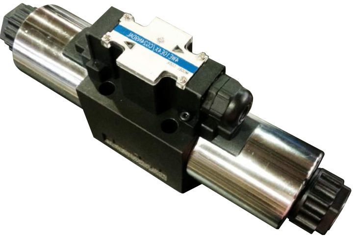
Model code breakdown
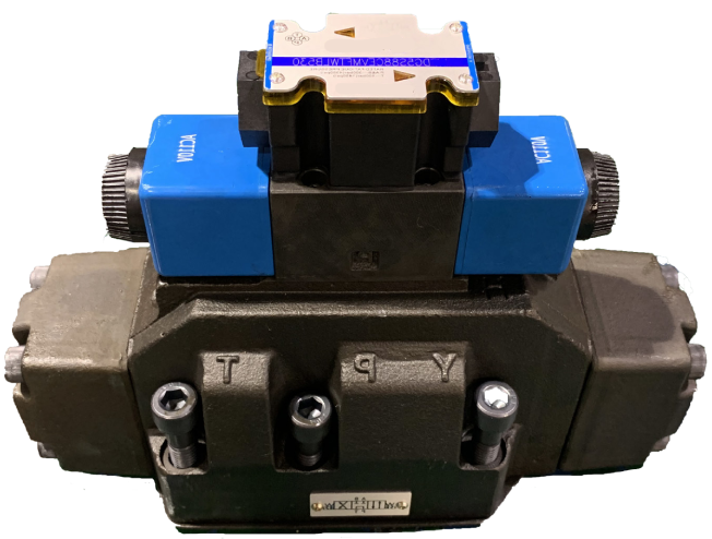
NG6/D03 and NG10/D05 directional control valve
- NG6/NG10 subplate-mounted directional valves
- Operating pressures 4,500 psi* for P-A-B
- Tank pressures up to 2,300 psi
- NG6/D03 flows up to 21 gpm
- NG10/D05 flows up to 32 gpm
4 WE 10 J 4X C W110 N9 DAL - - -
- 4
- 4 service ports
- 10
- Size NG10, NFPA D05
- J
- Spool
- 4X
- D05 series, 40 through 49
- C
- Solenoid, D05 size
- W110
- 110/120 V AC, 50/60 Hz
- N9
- Protected manual override
- DAL
- Conduit box with cable gland and lights
- -
- Port restrictions
- -
- Seals
- -
- Mounting-face alterations
Flow paths
| Description | Code |
|---|---|
| 3 service ports | 3 |
| 4 service ports | 4 |
Size
| Size | Code |
|---|---|
| NG6, NFPA D03 | 6 |
| NG10, NFPA D05 | 10 |
Spool options
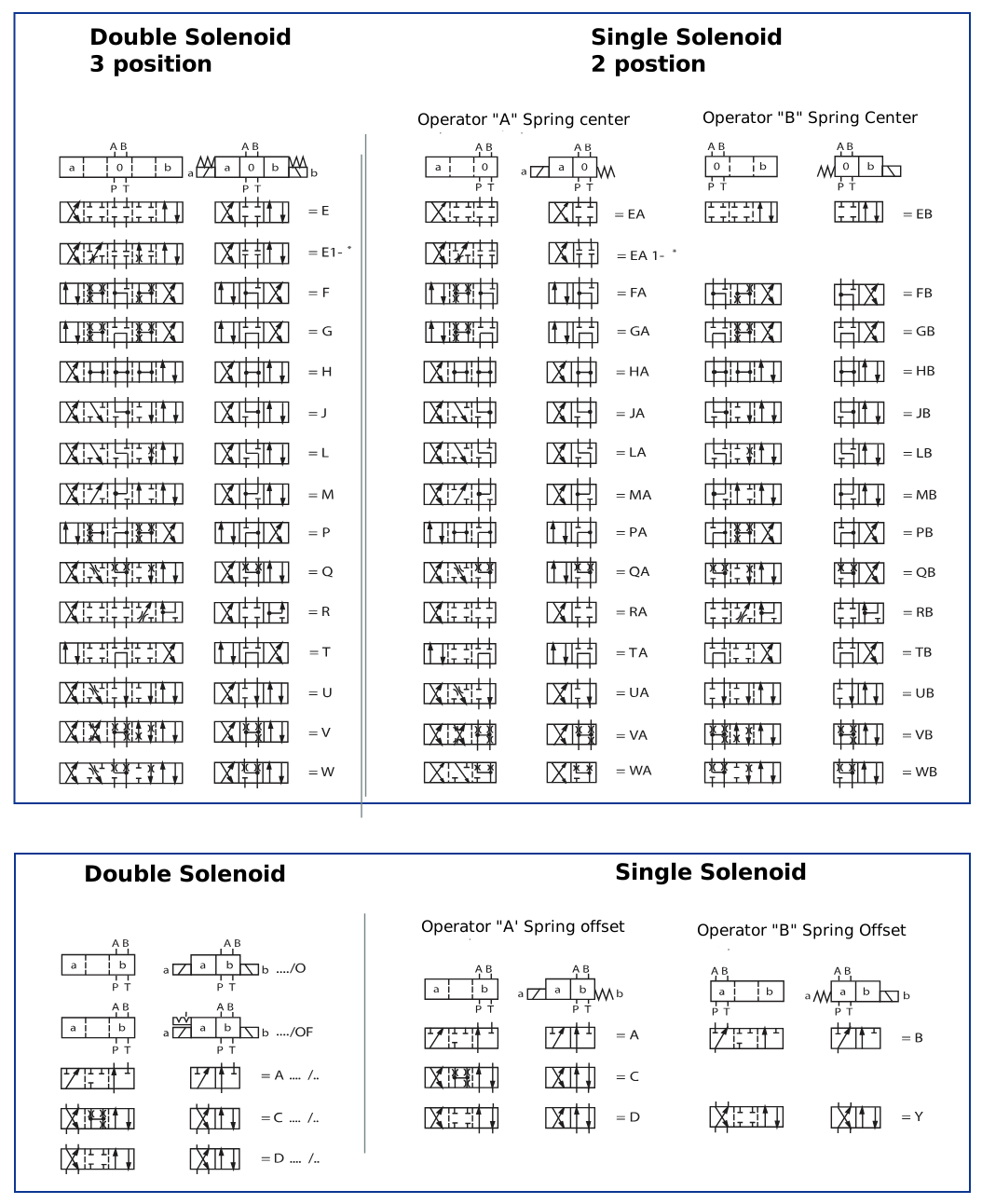
Spool, for example C, E, EA, EB, H, J, and so on. 1)
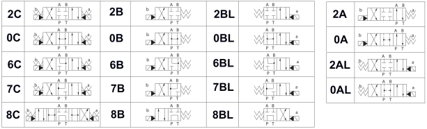
See the spool symbols for the options.
Series
| Series | Code |
|---|---|
| D03, series 60 through 69 | 6X |
| D05, series 30 through 39 (DIN connection) | 3X |
| D05, series 40 through 49 (conduit-box connection) | 4X |
De-energized condition
| Condition | Code |
|---|---|
| Spring return | No code |
| No spring return | O |
| Detented; no spring return | OF |
Solenoid type
High-performance solenoid, wet pin (oil immersed) with removable coil.
| Size | Code |
|---|---|
| D03 | E |
| D05 | C |
Coil voltage
| Voltage | Code |
|---|---|
| 12 V DC | G12 |
| 24 V DC | G24 |
| 96 V DC | G96 |
| 196 V DC | G196 |
| 110/120 V AC, 50/60 Hz | W110 |
| 220/240 V AC, 50/60 Hz | W220 |
| 96/196 V DC solenoid with rectifier built into the right-angle connector, for 110 V AC, frequency independent. Available with DIN RZ55 connector. | W110R |
| 96/196 V DC solenoid with rectifier built into the right-angle connector, for 220 V AC, frequency independent. Available with DIN RZ55 connector. | W220R |
Mounting-face alterations
| Description | Code |
|---|---|
| No locating hole (standard) | No code |
| With locating hole | /60 |
| With locating hole and pin | /62 |
Seals
| Description | Code |
|---|---|
| BR seals (standard) | No code |
| FKM seals | V |
Port restrictions
| Description | Code |
|---|---|
| No orifice insert (standard) | No code |
| Orifice Ø 0.031 (0.8 mm) | B08 |
| Orifice Ø 0.039 (1.0 mm) | B10 |
| Orifice Ø 0.047 (1.2 mm) | B12 |
Used when flow exceeds the valve performance limit. Location is the letter before the code: B- at port P, H- at port A, R- at port B, N- at ports A and B, X- at port T.
Direct solenoid electrical connections (DIN 24340 form A)
| Description | Code |
|---|---|
| No right-angle connector, with cap | K4 |
| Right-angle connector | Z45 |
| Right-angle connector with light | Z45L |
| Large right-angle connector with light | Z55L |
| Large right-angle connector with rectifier and light | RZ55L |
| Connector with light and Zener transient suppression | Z55L1 |
Central solenoid connections, wired box
| Description | Code |
|---|---|
| Conduit box with cable gland | DA |
| Conduit box with cable gland and lights | DAL |
Solenoid override
| Description | Code |
|---|---|
| With protected manual override (standard) | N9 |
| Covered manual override, with rubber boot | N |
| No manual override | No code |
1) See the spool configurations on the next page.
2) Series are externally interchangeable within the same decade (for example, 30-39).
*Maximum pressure for AC valves is 4,500 psi.
Maximum pressure for DC valves is 4,000 psi.
*All manufacturer names and part numbers are used for reference only.
Additional parts
D03 parts
| Part number | Description |
|---|---|
| Seal kits | |
| 86175 | 4WE6 Buna seal kit |
| 86176 | 4WE6 Viton seal kit |
| DIN coils | |
| 86137 | D03 DIN 4WE6 coil, 12 V DC |
| 86138 | D03 DIN 4WE6 coil, 24 V DC |
| 86245 | D03 DIN 4WE6 coil, 110R/(G96) V DC |
| 86246 | D03 DIN 4WE6 coil, 220R/(G196) V DC |
| 86140 | D03 DIN 4WE6 coil, 110 V AC |
| 86139 | D03 DIN 4WE6 coil, 220 V AC |
| Conduit-box coils | |
| 86144 | D03 4WE6 coil, 12 V DC, DAL wired |
| 86145 | D03 4WE6 coil, 24 V DC, DAL wired |
| 86159 | D03 4WE6 coil, 110 V AC, DAL wired |
| 86235 | D03 4WE6 coil, 220 V AC, DAL wired |
| AC/DC core tubes | |
| 86140-1 | D03 4WE6 AC core tube with knob |
| 86138-1 | D03 4WE6 DC core tube with knob |
D05 parts
| Part number | Description |
|---|---|
| Seal kits | |
| 86178 | 4WE10 Buna seal kit |
| 86179 | 4WE10 Viton seal kit |
| DIN coils | |
| 86122 | D05 DIN 4WE10 coil, 12 V DC |
| 86142 | D05 DIN 4WE10 coil, 24 V DC |
| 86243 | D05 DIN 4WE10 coil, W110R/(G96) V DC |
| 86244 | D05 DIN 4WE10 coil, W220R/(G196) V DC |
| 86143 | D05 DIN 4WE10 coil, 110 V AC |
| 86234 | D05 DIN 4WE10 coil, 220 V AC |
| Conduit-box coils | |
| 86151 | D05 4WE10 coil, 12 V DC, DAL wired |
| 86150 | D05 4WE10 coil, 24 V DC, DAL wired |
| AC/DC core tubes | |
| 86200 | D05 4WE10 AC core tube with knob |
| 86201 | D05 4WE10 DC core tube with knob |
Electrical DIN connectors
| Part number | Description |
|---|---|
| 86186 | DIN connector, 24 V DC, VDR transient suppressor |
| 86189 | DIN connector, 24 V AC/DC, rectifier + VDR suppressor |
| 86147 | DIN connector, 12/24 V DC with light |
| 86141 | DIN connector, 110/120 V AC with light |
| 86241 | DIN connector with rectifier, 110/120 V AC to 96 V DC |
| 86242 | DIN connector with rectifier, 220/240 V AC to 196 V DC |
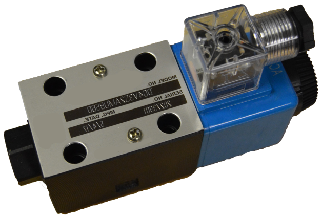
Model code breakdown
DG4V—3(S)—** *(L)—(**)—(V)M—(S*)—* ** * ** (L)—D *—6*—(EN***)—(P**—A**—B**—T**)
- 1
- DG4V
- Model series
- 2
- 3(S)
- Standard or high performance
- 3
- **
- Spool type
- 4
- *(L)
- Spring arrangement
- 5
- (**)
- Solenoid energization identity
- 6
- M
- Flag symbol
- 7
- (S*)
- Spool indicator switch
- 8
- *
- Coil type
- 9
- **
- Electrical connector
- 10
- *
- Housing, F coils only
- 11
- **
- Transient suppressor
- 12
- (L)
- Solenoid indicator lights
- 13
- D *
- Coil voltage
- 14
- 5, 6, 7
- Port T code
- 15
- 6*
- Design number
- 16
- (EN***)
- Special features
- 17
- (P**—A**—B**—T**)
- Port restrictor plugs
1. Model series
| Code | Description |
|---|---|
| D | Directional valve |
| G | Subplate or manifold mounting |
| 4 | Solenoid operated |
| V | 350 bar (5075 psi) pressure rating at ports P, A and B |
2. Standard or high performance
| Code | Description |
|---|---|
| 3* | High performance: up to 80 l/min (21 USgpm) at 350 bar (5075 psi) |
| 3S | Standard performance: up to 40 l/min (10.5 USgpm) at 350 bar (5075 psi) |
3. Spool type
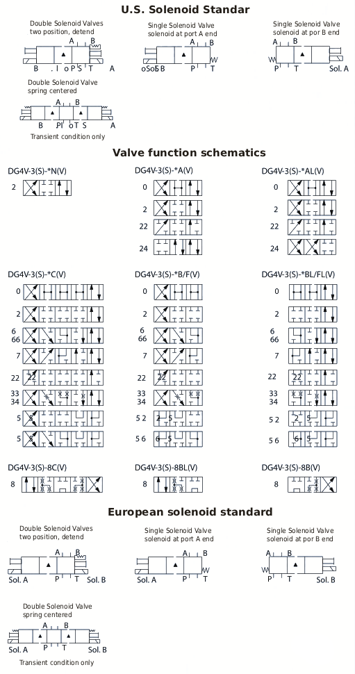
See the spool symbols.
4. Spool spring arrangement
| Code | Description |
|---|---|
| A | Spring offset, end to end |
| AL | Same as A, but left-hand build |
| B | Spring offset, end to center |
| BL | Same as B, but left-hand build |
| C | Spring centered |
| N* | No-spring, detented |
5. Solenoid energization identity
V — Solenoid A is at the port A end and/or solenoid B is at the port B end, depending on the spool type.
Omit for the U.S. standard ANSI B93.9, which requires energizing solenoid A to connect P to A and/or solenoid B to connect P to B, independent of solenoid location.
Type 8 spool valves meet both U.S. and European solenoid designations. When ordering a type 8 spool, include a V in the model code.
6. Flag symbol
M — Electrical options and features.
7. Spool indicator switch
Available on DG4V-3 high-performance models only. Omit if not required.
8. Coil type
| Code | Description |
|---|---|
| U | ISO 4400 (DIN 43650) mounting |
| U1 | With connector |
| U6 | With connector and lights |
| U11 | With connector, rectifier and lights |
| U12 | With connector and rectifier |
| F | 1/2" NPT conduit box |
9. Electrical connector
| Code | Description |
|---|---|
| T | Wired terminal strip |
| PA | Instaplug male receptacle |
| PB | Instaplug male and female receptacle |
| PA3 | Three-pin connector |
| PA5 | Five-pin connector |
10. Housing (F coils only)
W — 1/2" NPT conduit box.
11. Transient suppressor
| Code | Description |
|---|---|
| D1 | Encapsulated diode (industrial applications) |
| D2 | Encapsulated diode (mobile applications) |
| D7 | Transzorb type (U only) |
12. Solenoid indicator lights
L is available on U, U1, U6 and W.
13. Coil voltage
| Code | Description |
|---|---|
| A | 110 V AC 50 Hz |
| B | 110 V AC 50 Hz / 120 V AC 60 Hz |
| D | 220 V AC 50 Hz / 240 V AC 60 Hz |
| G | 12 V DC |
| H | 24 V DC |
Full-power coils. For 60 Hz or dual frequency.
14. Port T code
| Code | Description |
|---|---|
| 5 | 100 bar (1500 psi) for DG4V-3S standard-performance models, with AC or DC solenoids |
| 6 | 207 bar (3000 psi) for DG4V-3 AC high-performance models, including the S6 spool-position indicator |
| 7 | 207 bar (3000 psi) for DG4V-3 DC high-performance models, including the S6 spool-position indicator |
15. Design number
| Code | Description |
|---|---|
| 60 | Basic design |
| 61 | Type 8 spool |
16. Special features
The EN*** code is assigned as required.
EN21* — CSA-approved models with 1/2" NPT conduit box, type FW, and coil letter B, D, G or H.
17. Port restrictor plugs
Orifice size is shown in the model code. Plugs can be fitted by agreement. Omit if restrictor plugs are not fitted.
* Remanufactured only.
*All manufacturer names and part numbers are used for reference only.
Operating data
Performance data is typical with fluid at 36 cSt (168 SUS) and 50 °C (122 °F).
| Characteristic | DG4V3S standard-performance valve |
|---|---|
| Pressure limits | |
| Ports P, A and B | 310 bar (4500 psi) |
| Port T | 100 bar (1450 psi) |
| Rated flow | See the performance data |
| Relative duty factor | Continuous; ED = 100% |
| Protection type | |
| ISO 4400 coils with the connector fitted correctly | IEC 144 clase IP65 |
| Coil winding | Clase H |
| Leads (F*** coils) | Clase H |
| Coil encapsulation | Clase F |
| Permissible voltage fluctuation | |
| Maximum | See the temperature limits. |
| Minimum | 90% of rated |
| Typical response times at 100% of rated voltage, measured from voltage applied or removed to full shift of the 2C spool, at: | |
| Flow P-A, B-T | 20 l/min (5.3 USgpm) |
| Pressure | 175 bar (2537 psi) |
| AC energizing (~) | 18 ms |
| AC de-energizing (~) | 32 ms |
| DC energizing (=) | 60 ms |
| DC de-energizing (=) | 40 ms |
Power consumption, AC solenoids
For the coils named in the model code. Full-power coils.
| Coil | Inrush VA (RMS) | Holding VA (RMS) |
|---|---|---|
| Dual frequency at 50 Hz | 265 | 49 |
| Dual frequency at 60 Hz | 260 | 48 |
Power consumption, DC solenoids
At rated voltage and 20 °C (68 °F). Full-power coils.
| Coil | Power | Holding |
|---|---|---|
| 12 V, model type G | 30 W | – |
| 24 V, model type H | 30 W | – |
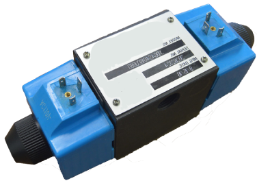
Model code breakdown
(F3) (PA5) DG4S 4 LW 01 8 C (U) B 60 (LH)
- (F3)
- Seal kit
- (PA5)
- Electrical connector options
- DG4S
- Model series
- 4
- Flow direction
- LW
- Electrical accessories
- 01
- Spool
- 8
- Spool types
- C
- Spool and spring arrangement
- (U)
- Wet-armature solenoid
- B
- Coil identification letter
- 60
- Design number
- (LH)
- Left-hand assembly
Seal kit
| Code | Description |
|---|---|
| F3 | Viton |
Electrical connector options
| Code | Description |
|---|---|
| PA3 | 3-pin NFPA connector |
| PA5 | 5-pin NFPA connector |
| Blank | Omit if not required |
Model series
DG4S — Directional control valve.
Flow direction
4 — 4 way.
Electrical accessories
| Code | Description |
|---|---|
| L | Solenoid indicator lights |
| W | Conduit box |
| LW | Conduit box with indicator lights |
| Blank | Omit if not required |
Spool
D05 reference.
Spool types
See the functional symbols.
Spool and spring arrangement
| Code | Description |
|---|---|
| A | Spring offset, P to A |
| B | Spring centered, solenoid “a” removed |
| C | Spring centered, three position |
Wet-armature solenoid
| Code | Description |
|---|---|
| Blank | Flying-lead coil |
| U | DIN 43650 coil without electrical connector |
Coil identification letter
See the solenoid table.
Solenoid
| Letter | Voltage | Inrush A (rms) | Holding A (rms) | Holding W |
|---|---|---|---|---|
| B | 120 V CA 60 Hz | 3.80 | 0.69 | 35 |
| B | 110 V AC 50 Hz | 4.10 | 0.85 | 33 |
| D | 240 V CA 60 Hz | 2.10 | 0.34 | 36 |
| D | 220 V AC 50 Hz | 2.30 | 0.45 | 34 |
| G | 12 V DC | – | 3.67 | 44 |
| H | 24 V DC | – | 1.83 | 44 |
Design number
Subject to change. Installation dimensions remain as shown for designs 60 through 69.
Left-hand assembly
Omit for the right-hand assembly, with solenoid “a” removed.
Mounting subplates
See the installation dimensions and the ordering procedure.
*All manufacturer names and part numbers are used for reference only.
Basic characteristics
| Maximum pressure | Up to 248 bar (3600 psi), depending on the fluid |
| Maximum flows | Up to 95 l/min (25 USgpm), depending on the spool |
| Mounting pattern | ISO 4401-05 / CETOP 5 / NFPA-D05 |
DG4S* models are 4-way directional valves operated directly by a solenoid. In a hydraulic circuit their main job is to direct flow to a working cylinder or to control the direction of a hydraulic motor. Port connections are made by mounting the valve on a manifold or on a subplate that carries the interface.
Valves are available with a wet-armature AC or DC solenoid. Electrical connections are made in a conduit box or by plug-in devices. A ground terminal is included.
Functional symbols
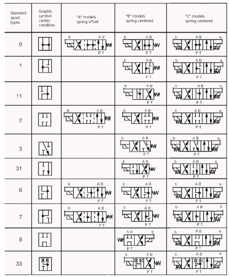
The standard (right-hand) assembly is shown. Solenoid “A” is omitted.
When solenoid “a” is energized, flow goes from “P” to “A”. When solenoid “b” is energized, flow goes from “P” to “B”. This meets ANSI-B93.9.
Solenoids “a” and “b” are identified on the diagram plate on the side of the valve.
Maximum pressure
| Port | Pressure |
|---|---|
| P, A and B | 248 bar (3600 psi) |
| T | 100 bar (1450 psi) |
Solenoid energization
Spring-centered and spring-offset valves stay in the spring position unless the solenoid is energized continuously.
Any sliding-spool valve held shifted under pressure for long periods can stick and fail to spring-return, because of silt. Cycle the valve periodically to prevent that.
Response time
Times are measured from energizing or de-energizing to the first change in inlet pressure. Time to full system pressure depends on the compressed volume and varies with each application.
| Model | Valve type | AC shift | AC return | DC shift | DC return |
|---|---|---|---|---|---|
| B/C | Spring centered | 20 ms | 40 ms | 50 ms | 80 ms |
| A | Spring offset | 18 ms | 25 ms | 50 ms | 60 ms |
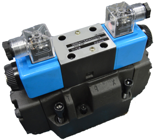
Model code breakdown
DG5S * * * (*) -(*)-(E) - (T) (*)- ( ) M- * (**)* * (L)-** *- 30/40
- 1
- DG5S
- Model series
- 2
- *
- Interface
- 3
- *
- Spool type
- 4
- *
- Spool and spring arrangement
- 5
- (*)
- Left-hand assembly
- 6
- -
- Manual override
- 7
- (*)
- Response type
- 8
- -
- Spool control modifications
- 9
- (E)
- Pilot pressure
- 10
- (T)
- Pilot drain
- 11
- (*)
- Pressure-port check valve
- 12
- ( )
- Solenoid energization identity
- 13
- M
- Flag symbol
- 14
- *
- Coil type
- 15
- (**)
- Electrical connections
- 16
- *
- Housing
- 17
- *
- Electrical options
- 18
- (L)
- Solenoid indicator lights
- 19
- **
- Coil identification
- 20
- *
- Pilot valve tank pressure rating
- 21
- 30/40
- Design number
1. Model series
| Code | Description |
|---|---|
| D | Directional control valve |
| G | Subplate or manifold mounting |
| 5 | Solenoid controlled, pilot operated |
| S | Sliding spool, 210 bar (3000 psi) pressure rating |
2. Interface
| Code | Description |
|---|---|
| 4-04 | D07, NFPA |
3. Spool type
| Code | Center position |
|---|---|
| 0 | All ports open |
| 2 | All ports closed |
| 4 | Tandem, P to T, A and B closed |
| 6 | P closed, A and B to T |
| 7 | P open to A and B, T closed |
| 8 | Tandem, P to T, A and B closed |
Functional symbols are on the catalog spool diagram.
4. Spool and spring arrangement
| Code | Description |
|---|---|
| A | Spring offset to port A |
| B | Spring centered, solenoid A removed |
| C | Spring centered |
| N | No-spring, detented (pilot only) |
5. Left-hand assembly
| Code | Description |
|---|---|
| L | Left hand, single solenoid only. For the right-hand assembly, P to port A when solenoid A is energized. |
| Blank | Omit if not required |
6. Manual override
| Code | Description |
|---|---|
| Blank | Plain manual override, at the solenoid ends only |
7. Response type
| Code | Description |
|---|---|
| X | Fast response |
| Blank | Standard low-shock models |
8. Spool control modifications
| Code | Description |
|---|---|
| 2 | Dual pilot choke adjustment |
| Blank | Omit if not required |
9. Pilot pressure
| Code | Description |
|---|---|
| E | External pilot pressure |
| Blank | Internal pilot pressure |
10. Pilot drain
| Code | Description |
|---|---|
| T | Internal pilot drain |
| Blank | External pilot drain |
11. Pressure-port check valve
| Code | Description |
|---|---|
| K | 5 psi cracking pressure |
| R | 50 psi cracking pressure |
| S | 75 psi cracking pressure |
| Blank | Omit if not required |
12. Solenoid energization identity
| Code | Description |
|---|---|
| V | Solenoid identity is set by position: solenoid A at the port A end and/or solenoid B at the port B end |
| Blank | Standard ANSI B93.9 arrangement: energize solenoid A for flow from P to port A |
V code for any valve with spool 4 or 8.
13. Flag symbol
M — Electrical options and features.
14. Coil type
| Code | Description |
|---|---|
| F | Flying leads |
| U | DIN ISO 4400 |
15. Electrical connections (F coil only)
| Code | Description |
|---|---|
| T | Wired terminal strip |
| PA3 | Three-pin connector |
| PA5 | Five-pin connector |
| Blank | Omit if not required |
16. Housing (F coil only)
| Code | Description |
|---|---|
| W | 1/2" NPT conduit box |
| Blank | Omit if not required |
17. Electrical options (U coil only)
Blank — ISO with plug fitted and lights.
18. Solenoid indicator lights (F coil with T connections only)
| Code | Description |
|---|---|
| L | Indicator lights |
| Blank | Omit if not required |
19. Coil identification
| Code | Description |
|---|---|
| B | 110 V AC 50 Hz / 120 V AC 60 Hz |
| D | 220 V AC 50 Hz / 240 V AC 60 Hz |
| G | 12 V DC |
| H | 24 V DC |
20. Pilot valve tank pressure rating
| Code | Description |
|---|---|
| 5 | 1450 psi, DG4V3S-60 |
| 6 | 3045 psi, DG4V3-60 with AC solenoids, high performance |
| 7 | 3000 psi, DG4V3-60 with DC solenoids, high performance |
21. Design number
Subject to change.
*All manufacturer names and part numbers are used for reference only.
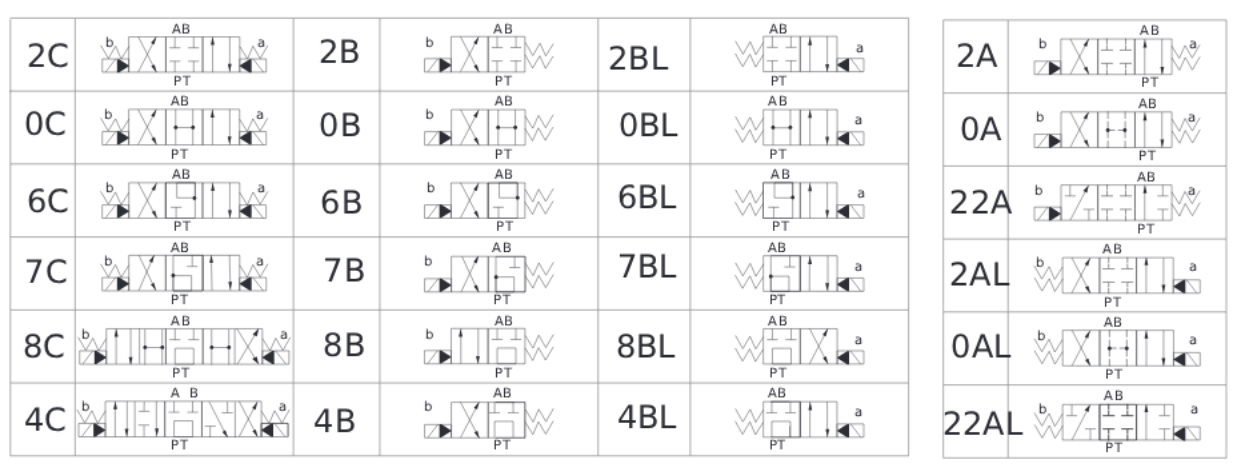
Spool type and spring mechanism
Technical data
| D07 | Weight |
|---|---|
| Valve with one solenoid | 14 lbs |
| Valve with two solenoids, spring centered | 15 lbs |
Maximum operating pressure
| Ports | Type | psi | Voltage |
|---|---|---|---|
| P, A, B | Pressure | 4061 | |
| T | External Y pilot-oil drain | 3626 | |
| T | Internal Y pilot-oil drain | 3046 | CC |
| T | Internal Y pilot-oil drain | 2320 | CA |
| Y | External pilot-oil drain | 3046 | CC |
| Y | External pilot-oil drain | 2320 | CA |
| Maximum pilot pressure | 3600 |
D03 pilot coils
| Rated voltage | Hz | Working voltage | Inrush current | Holding current | Power (W) | Note |
|---|---|---|---|---|---|---|
| DC12 | 10.8–13.2 | 2.5 A | 30 | |||
| DC24 | 21.6–26.4 | 1.25 A | 30 | |||
| AC110B | 99–121 | 0.65 A | 30 | Rectified type | ||
| AC220B | 198–242 | 0.33 A | 30 | Rectified type | ||
| AC110V | 50/60 | 99–121 | 1.7 A | 0.48 A | 30 | |
| AC220V | 50/60 | 198–242 | 0.85 A | 0.25 A | 30 |
Model code breakdown
DG5- ** * * (*) -(*)-(E) - (T) (*)- ( ) M-(S*) * (**)* * (L)-** 5- *** 60/70
- 1
- DG5-
- Model series
- 2
- **
- Interface
- 3
- *
- Spool type
- 4
- *
- Spool and spring arrangement
- 5
- (*)
- Left-hand assembly
- 6
- -
- Manual override
- 7
- (*)
- Response type
- 8
- -
- Spool control modifications
- 9
- (E)
- Pilot pressure
- 10
- (T)
- Pilot drain
- 11
- (*)
- Pressure-port check valve
- 12
- ( )
- Solenoid energization identity
- 13
- M
- Flag symbol
- 14
- (S*)
- Spool indicator switch
- 15
- *
- Coil type
- 16
- (**)
- Electrical connections
- 17
- *
- Housing
- 18
- *
- Electrical options
- 19
- (L)
- Solenoid indicator lights
- 20
- **
- Coil identification
- 21
- 5-
- Pilot valve tank pressure rating
- 22
- ***
- Pilot valve port orifices
- 23
- 60/70
- Design number
1. Model series
| Code | Description |
|---|---|
| D | Directional control valve |
| G | Subplate or manifold mounting |
| 5 | Solenoid controlled, pilot operated |
2. Interface
| Code | Description |
|---|---|
| S8 | D08 |
| SH8 | D08H |
3. Spool type
| Code | Center position |
|---|---|
| 0 | All ports open to T |
| 1* | P and A open to T, B closed |
| 2 | All ports closed to T |
| 3 | P and B closed, A open to T |
| 4 | Tandem, P to T, closed to P crossover |
| 6 | P closed only, A and B to T |
| 7 | P open to A and B, T closed |
| 8 | Tandem, P to T, open crossover |
| 9* | All ports open to T, on cones |
| 11* | P and B open to T, A closed |
| 31 | P and A closed, B open to T |
| 33 | P closed, A and B to T on cones |
4. Spool and spring arrangement
| Code | Description |
|---|---|
| A | Spring offset to port A |
| B | Spring centered, solenoid A removed |
| C | Spring centered |
5. Left-hand assembly
| Code | Description |
|---|---|
| L | Left hand, single solenoid at the A end. For the right-hand assembly, omit. P to port A when solenoid A is energized. |
| Blank | Omit if not required |
6. Manual override
| Code | Description |
|---|---|
| Blank | Plain manual override, at the solenoid ends only |
7. Response type
| Code | Description |
|---|---|
| X* | Fast response |
| Blank | Standard low-shock models |
8. Spool control modifications
| Code | Description |
|---|---|
| 1* | Stroke adjustment at both ends |
| 2 | Dual pilot choke adjustment |
| 3* | Pilot choke and stroke adjustment |
| 7* | Stroke adjustment at the port A end only |
| 8* | Stroke adjustment at the port B end only |
| 2-7* | Dual pilot choke and stroke adjustment at the port A end only |
| 2-8* | Dual pilot choke and stroke adjustment at the port B end only |
| Blank | Omit if not required |
9. Pilot pressure
| Code | Description |
|---|---|
| E | External pilot pressure |
| Blank | Internal pilot pressure |
10. Pilot drain
| Code | Description |
|---|---|
| T | Internal pilot drain |
| Blank | External pilot drain |
11. Pressure-port check valve
| Code | Description |
|---|---|
| K* | 5 psi cracking pressure |
| R* | 50 psi cracking pressure |
| S | 75 psi cracking pressure |
| Blank | Omit if not required |
12. Solenoid energization identity
| Code | Description |
|---|---|
| V | Solenoid identity is set by position: solenoid A at the port A end and/or solenoid B at the port B end |
| Blank | Standard ANSI B93.9 arrangement: energize solenoid A for flow from P to port A |
V code for any valve with spool 4 or 8.
13. Flag symbol
M — Electrical options and features.
14. Spool indicator switch
| Code | Description |
|---|---|
| S3 | Normally open (P* code valves only) |
| S4 | Normally closed (P* code valves only) |
| S5 | Flying leads (F coil valves only) |
| S6 | DC LVDT-type switch |
Available on DG4V3 high-performance pilot models only.
15. Coil type
| Code | Description |
|---|---|
| U | ISO 4400 |
| F | Flying leads |
16. Electrical connections (F coil only)
| Code | Description |
|---|---|
| T* | Wired terminal strip |
| PA* | Instaplug male receptacle only |
| PB* | Instaplug male and female receptacle |
| PA3 | Three-pin connector |
| PA5 | Five-pin connector |
| Blank | Omit if not required |
17. Housing (F coil only)
| Code | Description |
|---|---|
| W | 1/2" NPT conduit box |
| Blank | Omit if not required |
18. Electrical options (U coil only)
Blank — ISO with plug fitted and lights.
19. Solenoid indicator lights (F coil with T connections only)
| Code | Description |
|---|---|
| L | Indicator lights |
| Blank | Omit if not required |
20. Coil identification
| Code | Description |
|---|---|
| A* | 110 V AC 50 Hz |
| B | 110 V AC 50 Hz / 120 V AC 60 Hz* |
| C* | 220 V AC 50 Hz |
| D | 220 V AC 50 Hz / 240 V AC 60 Hz* |
| G | 12 V DC |
| H | 24 V DC |
| DJ* | 98 V DC |
| P* | 110 V DC |
21. Pilot valve tank pressure rating
| Code | Description |
|---|---|
| 2* | 10 bar (145 psi), WFDG4V3S-60 with spool indicator switch S3, S4 or S5 |
| 5 | 100 bar (1450 psi), WFDG4V3S-60 |
| 6 | 160 bar (2300 psi), with WF4WE6-6X and AC solenoids |
| 7 | 210 bar (3000 psi), WF4WE6-6X with DC solenoids |
22. Pilot valve port orifices
| Code | Orifice diameter |
|---|---|
| *00 | Solid plug |
| *03 | 0,30 mm (0,012 in) |
| *06 | 0,60 mm (0,024 in) |
| *08 | 0,80 mm (0,030 in) |
| *10 | 1,00 mm (0,040 in) |
| *13 | 1,30 mm (0,050 in) |
| *15 | 1,50 mm (0,060 in) |
| *20 | 2,00 mm (0,080 in) |
| *23 | 2,30 mm (0,090 in) |
| Blank | Omit if not required |
* = P, T, A and/or B, as required.
23. Design number
| Code | Description |
|---|---|
| 60 | WFDG4V3S-60 pilot valve (standard performance) |
| 70 | WF4WE6-6X pilot valve (high performance) |
* Available in remanufactured only.
*All manufacturer names and part numbers are used for reference only.
Spool type and spring mechanism
Pilot pressure technical data
| Style | Size NG 22 | Size NG 25 |
|---|---|---|
| Vickers | DG5S8 | DG5SH8 |
| TU | TUDG5S8 | TUDG5SH8 |
| Rexroth | 4WH 22 | 4WH 25 |
| TU | TU4WEH22 | TU4WEH25 |
Pilot oil supply
| Supply | Position | psi | 22 | 25 |
|---|---|---|---|---|
| External X | 3-position valve, spring centered | psi | 152 | 188 |
| External X | 3-position valve, pressure centered | psi | — | 261 |
| External X | 2-position valve, spring end position | psi | 159 | 188 |
| External X | 2-position valve, hydraulic end position | psi | 116 | 116 |
| Internal X | psi | 65 | 65 |
Valves must be installed horizontally.
Filtered hydraulic oil must be 20 microns or finer.
Model code breakdown
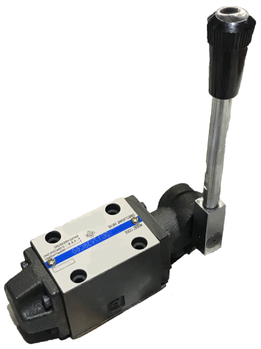
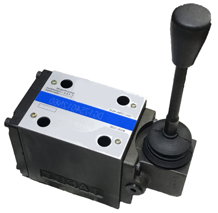
D03 (NG6) directional control valve. Flow is 15 gpm and maximum operating pressure is 4500 psi.
- 1
- DG
- Series
- 2
- 17
- Manual operation
- 3
- V
- Pressure rating
- 4
- 3
- Interface
- 5
- 0
- Spool type
- 6
- A
- Spool spring arrangement
- 7
- 60
- Design
1. Series
| Code | Description |
|---|---|
| DG | Directional control valve, subplate or manifold mounting |
2. Manual operation
| Code | Description |
|---|---|
| 17 | Lever |
3. Pressure rating
| Code | Description |
|---|---|
| V | 315 bar (4500 psi) |
4. Interface
| Code | Description |
|---|---|
| 3 | ISO-4401-03, NFPA-D03 |
5. Spool type
| Code | Description |
|---|---|
| 0, 2, 6 and 8 | See the spool table |
6. Spool spring arrangement
| Code | Description |
|---|---|
| A | Spring offset |
| C | Spring centered |
| N | No-spring, detented |
7. Design
60
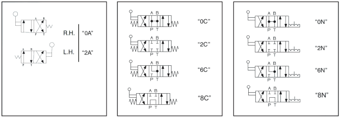
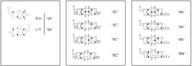
Spool type
2-position, spring offset
| Assembly | Code |
|---|---|
| Right-hand (R.H.) | 0A |
| Left-hand (L.H.) | 2A |
3-position, spring centered
| Code |
|---|
| 0C |
| 2C |
| 6C |
| 8C |
3-position, detented
| Code |
|---|
| 0N |
| 2N |
| 6N |
| 8N |
*All manufacturer names and part numbers are used for reference only.
Spool type
2-position, spring offset
Right-hand (R.H.) — 0A
Left-hand (L.H.) — 2A
3-position, spring centered
0C
2C
6C
8C
3-position, detented
0N
2N
6N
8N
Model code breakdown
D05 (NG10) directional control valve. Flow is 26 gpm and maximum operating pressure is 4500 psi.
- 1
- DG
- Series
- 2
- 17
- Manual operation
- 3
- S4
- Pressure rating
- 4
- 01
- Interface
- 5
- 0
- Spool type
- 6
- A
- Spool spring arrangement
- 7
- 60
- Design
1. Series
| Code | Description |
|---|---|
| DG | Directional control valve, subplate or manifold mounting |
2. Manual operation
| Code | Description |
|---|---|
| 17 | Lever |
3. Pressure rating
| Code | Description |
|---|---|
| S4 | 315 bar (4500 psi) |
4. Interface
| Code | Description |
|---|---|
| 01 | ISO-4401-05, NFPA-D05 |
5. Spool type
| Code | Description |
|---|---|
| 0, 2, 6 and 8 | See the spool table |
6. Spool spring arrangement
| Code | Description |
|---|---|
| A | Spring offset |
| C | Spring centered |
| N | No-spring, detented |
7. Design
60
Spool type
2-position, spring offset
| Assembly | Code |
|---|---|
| Right-hand (R.H.) | 0A |
| Left-hand (L.H.) | 2A |
3-position, spring centered
| Code |
|---|
| 0C |
| 2C |
| 6C |
| 8C |
3-position, detented
| Code |
|---|
| 0N |
| 2N |
| 6N |
| 8N |
*All manufacturer names and part numbers are used for reference only.
Spool type
2-position, spring offset
Right-hand (R.H.) — 0A
Left-hand (L.H.) — 2A
3-position, spring centered
0C
2C
6C
8C
3-position, detented
0N
2N
6N
8N
Industrial hydraulic directional valves: replacements and applications
Industrial hydraulic directional valves start, stop, and set the direction of actuator movement in a hydraulic system. By directing oil flow to different ports, they extend or retract hydraulic cylinders, reverse hydraulic motors, and control the movements of industrial machines.
Technical Union (TU) supplies hydraulic directional valves for industrial applications, including standardized mounting options that can replace existing valves from different manufacturers, depending on the required configuration and specifications. We supply solutions for industrial maintenance, machinery repair, equipment builders, and hydraulic-component distributors in Latin America.
Standard-mounting hydraulic directional valves
When a hydraulic valve has to be replaced, keeping the existing mounting interface can simplify the repair and reduce the need to modify the manifold or the piping.
Subplate-mounted directional valves, available in standardized sizes such as NG6/D03 and NG10/D05, are widely used in industrial hydraulic systems. These sizes match standardized interfaces, which makes it easier to find compatible alternatives across manufacturers.
Depending on the model and its technical characteristics, a replacement valve can be an alternative for equipment that uses components from brands such as:
- Bosch Rexroth
- Eaton Vickers
- Parker Hannifin
- Yuken
- Other industrial directional-valve brands
Compatibility has to be confirmed from the mounting size and pattern, the hydraulic schematic, the spool type, the working pressure, the rated flow, and the actuator. Electrical connections, coil voltage, and spring-return or detent options also have to be checked when they apply.
If you need to replace an existing hydraulic directional valve, send us the brand, the model, or the part number. We can review the available data and help identify a suitable alternative for your application.
Industries that use hydraulic directional valves
Directional valves are found in a wide range of industrial hydraulic circuits, in production machinery and in equipment for handling, forming, and processing materials.
Metalworking and industrial manufacturing
In industrial shops and manufacturing plants, directional valves control the hydraulic movements of machines used to clamp, position, lift, and press parts.
Applications and machines:
- Industrial hydraulic presses.
- Metal stamping and forming machines.
- Hydraulic clamping and fixturing equipment.
- Metal cutting and processing machines.
- Hydraulic positioning systems.
- Equipment for manufacturing metal components.
- Hydraulic devices for production lines.
Plastics and rubber
Hydraulic systems generate and control high-force movements in different polymer-processing machines.
Applications and machines:
- Plastic injection-molding machines.
- Rubber compression presses.
- Industrial molding machines.
- Hydraulic mold open-and-close systems.
- Part clamping and ejection equipment.
- Auxiliary machinery for plastics processing.
Machinery and industrial automation
Directional valves control the hydraulic actuators built into automatic machines, special equipment, and production lines.
Applications and machines:
- Special-purpose industrial manufacturing machines.
- Part handling and positioning systems.
- Automated assembly equipment.
- Hydraulic test stands.
- Cylinder actuation systems.
- Production equipment with hydraulic sequences.
- Hydraulic power units for industrial machinery.
Mining and mineral processing
In mining and material-processing hydraulic systems, directional valves control actuators used for opening, closing, lifting, and positioning.
Applications and machines:
- Mineral crushing and processing equipment.
- Hydraulic material-feed systems.
- Mining maintenance and repair equipment.
- Positioning and clamping systems.
- Auxiliary industrial equipment for processing plants.
- Material-handling machinery.
Wood, paper, and packaging
Hydraulic valves are also used in equipment for converting, feeding, pressing, and handling materials.
Applications and machines:
- Industrial presses for wood.
- Board-processing equipment.
- Cutting and feeding machines.
- Hydraulic compacting systems.
- Paper manufacturing and processing equipment.
- Industrial packaging and material-converting machinery.
Power and industrial process equipment
Hydraulic actuators operate mechanisms that need high force and controlled movement in different industrial installations.
Applications and machines:
- Hydraulic positioning systems.
- Gate-actuation equipment.
- Clamping and closing systems.
- Hydraulic units for process machinery.
- Industrial maintenance equipment.
- Auxiliary hydraulic systems for power and processing installations.
Hydraulic applications and control functions
The same family of directional valves can be used on different equipment, as long as the design and the operating conditions fit the application.
Common functions include:
Hydraulic cylinder control: directing flow to extend and retract single- or double-acting cylinders, depending on the circuit.
Hydraulic motor control: reversing or selecting the direction of rotation with a suitable valve configuration.
Workpiece clamping: operating jaws, fixtures, and positioning devices on industrial machines.
Raising and lowering: directional control of hydraulic actuators on handling equipment and industrial machinery.
Pressing and forming: control of hydraulic movements on presses and manufacturing equipment.
Sequence automation: operating cylinders and other actuators with electrical valves tied into the machine controls.
Maintenance and repair: replacing worn, damaged, or discontinued valves so an existing hydraulic system can run again.
Manual valves and solenoid-operated valves
The actuator is selected from the circuit design and from the way the machine is controlled.
Manual directional valves are operated with a lever or another manual mechanism. They fit applications where the operator controls the hydraulic movement directly.
Solenoid-operated directional valves use an electrical coil to shift the spool. They are used on automated machinery, electrical control systems, and equipment that needs remote actuation.
The spool configuration, the number of ways and positions, spring return, detents, and the available actuator options also have to be selected correctly.
How to select a replacement hydraulic directional valve
To identify a suitable alternative, gather the following information from the installed valve:
- Brand and part number: the full reference of the original valve, if it is available.
- Mounting size: for example NG6/D03 or NG10/D05, when it applies.
- Spool schematic: the port connections in each working position.
- Pressure and flow: the circuit working conditions and the required capacity.
- Actuator type: manual, solenoid, or another configuration.
- Electrical characteristics: voltage, current type, and connections, for electrical valves.
- Operating conditions: hydraulic fluid, temperature, and sealing requirements.
A matching mounting pattern does not by itself guarantee interchangeability. The selected valve has to meet the hydraulic, functional, and electrical requirements of the equipment.
Industrial hydraulic valves from Technical Union
Technical Union helps industrial companies, hydraulic distributors, repair shops, and machinery builders identify components for maintenance, replacement, and repair of hydraulic systems.
We supply hydraulic components from the United States to customers in Latin America. If you are looking for an industrial directional valve compatible with a Bosch Rexroth, Eaton Vickers, Parker, or other brand valve, we can review the original reference and the requirements of your application.
Request a quote for your hydraulic directional valve. Send the part number, a photo of the nameplate, or the manufacturer reference, together with the specifications you have. That lets us evaluate suitable replacement options for your machine or hydraulic system.
Contact Technical Union to ask about availability, replacement alternatives, and supply of industrial hydraulic valves for your market.