Modular Valves

DGMC3 41 and DGMC23 41
Module height 40 mm. D03 mounting. Removable hand knob. 18-month warranty.
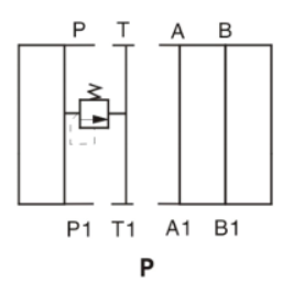
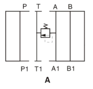
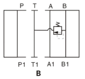
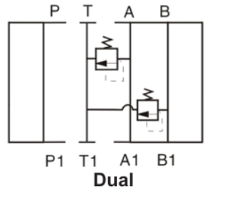
The relief valve dumps system pressure from line A, B, or P to line T. Pressure is set on the valve with knobs.
Model code breakdown
- 1
- DGMC
- Relief valve
- 2
- 2
- Type
- 3
- 3AT
- First function
- 4
- B
- Pressure adjustment range, first function
- 5
- H
- Adjustment and lock method, first function
- 6
- BT
- Second function
- 7
- B
- Pressure adjustment range, second function
- 8
- H
- Adjustment and lock method, second function
- 9
- 41
- Series 41
Relief valve
DGMC
Type
| Code | Description |
|---|---|
| 2 | Dual relief function |
| — | Omit for single relief function |
First function
Single relief, or the first line of dual models. In the example, 3 is the D03 size and AT is the function code.
| Code | Pressure limited at | Relieves to | Use |
|---|---|---|---|
| PT | P | T | Single only |
| AB* | A | B | Single, or dual with BA |
| BA | B | A | Single only |
| AT | A | T | Single, or dual with BT |
| BT | B | T | Single only |
Pressure adjustment range, first function
| Code | Range |
|---|---|
| B | 3-100 bar (45-1450 psi) |
| C | 10-200 bar (145-2900 psi) |
| G | 50-315 bar (725-4500 psi) |
Adjustment and lock method, first function
| Code | Description |
|---|---|
| H | Knob |
| W* | Screw with locknut |
Second function
Second line of dual models. Omit on single-line models.
| Code | Pressure limited at | Relieves to | Use |
|---|---|---|---|
| BA* | B | A | Dual with AB |
| BT | B | T | Dual with AT |
Pressure adjustment range, second function
| Code | Range |
|---|---|
| B | 3-100 bar (45-1450 psi) |
| C | 10-200 bar (145-2900 psi) |
| G | 50-315 bar (725-4500 psi) |
Adjustment and lock method, second function
| Code | Description |
|---|---|
| H | Knob |
| W* | Screw with locknut |
Series 41
Subject to change.
* Available in Reman only.
Operation
*All manufacturer names and part numbers are used for reference only.
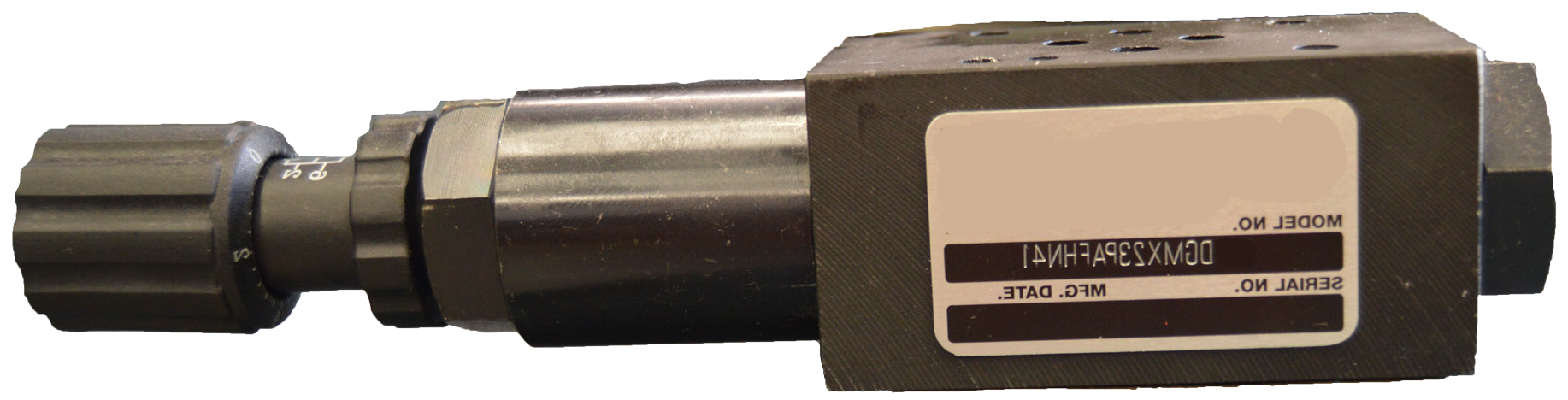
DGMX23 40
Module height 40 mm. D03 mounting. Removable hand knob. 18-month warranty.
Pressure reducing valves hold a reduced outlet pressure regardless of inlet pressure. Pressure is reduced in line P and set with the knob.
The pressure reducing valve passage is normally open. If pilot pressure is higher than the valve setting, the spring closes the valve.
Model code breakdown
Pressure reducing valve
DGMX23
Function ports
| Code | Description |
|---|---|
| PA | Pressure reducing function in line P, piloted from A |
| PB | Pressure reducing function in line P, piloted from B |
| PP | Pressure reducing function in line P, piloted from P |
Pressure adjustment range
| Code | Range |
|---|---|
| B | 3.5-70 bar (50-1000 psi) |
| C | 10-140 bar (145-2000 psi) |
| F | 20-250 bar (290-3625 psi) |
Series 40
Subject to change.
Operation
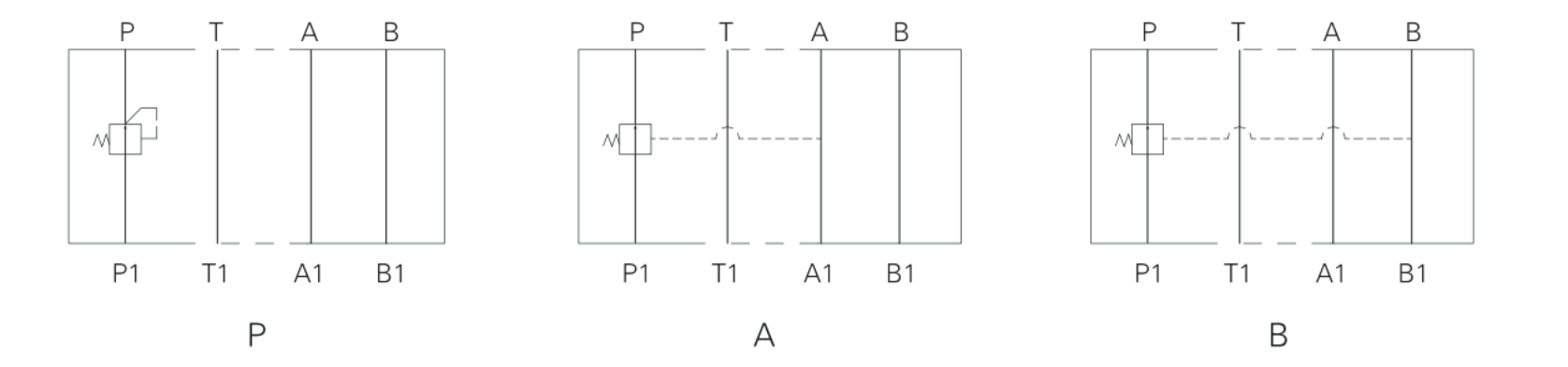
*All manufacturer names and part numbers are used for reference only.
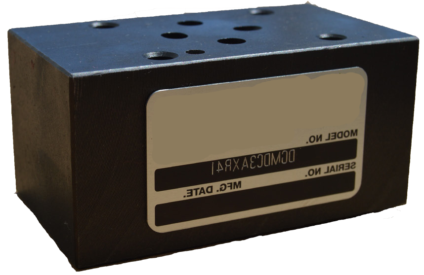
DGMDC3 41
Module height 40 mm. D03 mounting. Same-day shipping. 18-month warranty.
These valves allow free flow in one direction and block flow in the opposite direction.
Model code breakdown
Direct check valve
DGMDC3
Flow direction
| Code | Description |
|---|---|
| X | Free flow away from the actuator |
| Y | Free flow toward the actuator |
Check location
| Code | Description |
|---|---|
| A | Line A |
| B | Line B |
| P | Line P, with free flow toward the actuator (Y in 1) |
| T | Line T, with free flow away from the actuator (X in 1) |
Cracking pressure
| Code | Pressure |
|---|---|
| L | 5 psi (0.34 bar) |
| R | 60 psi (4.14 bar) |
Series 41
Subject to change.
Operation
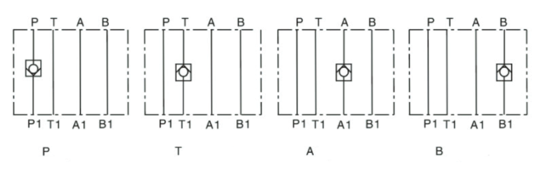
*All manufacturer names and part numbers are used for reference only.
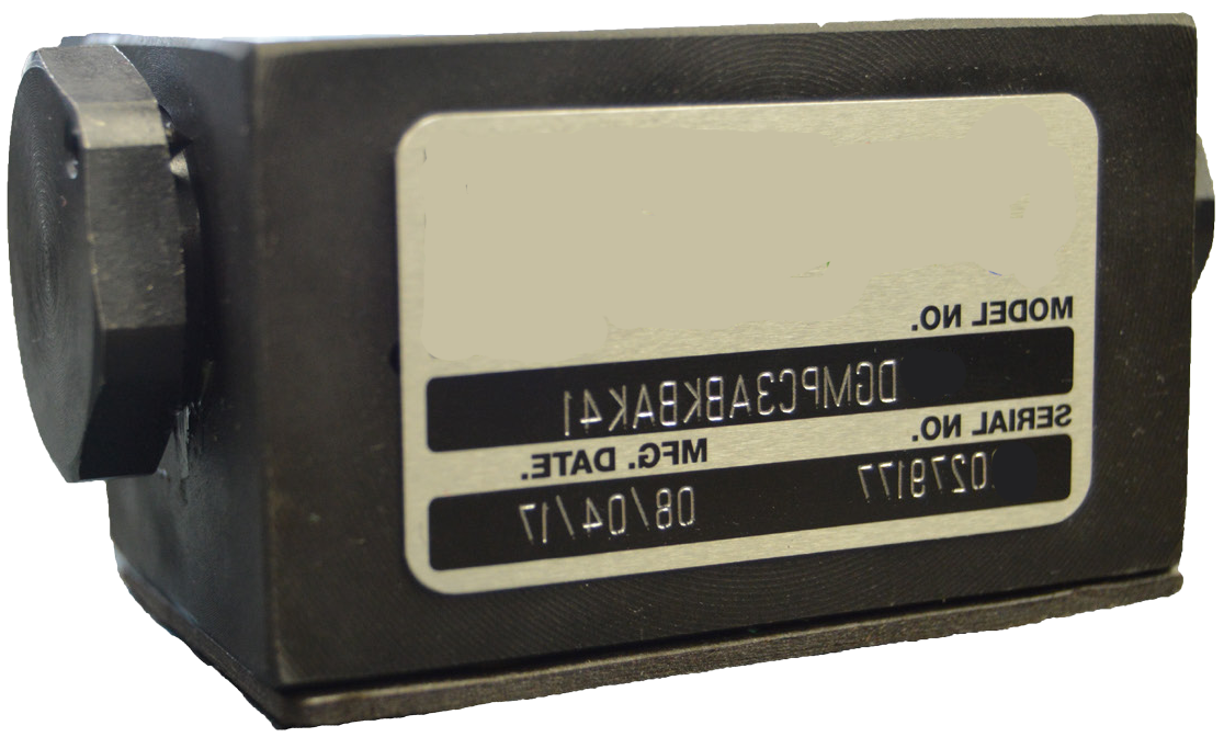
DGMPC3 41
Module height 40 mm. D03 mounting. Cracking pressure 14.5 psi (1 bar). 18-month warranty.
These valves allow flow through one or both service lines A or B, and let flow travel the opposite way through the other service line by a pilot operated check. If there is pressure in one service line, the check valve opens in the other service line.
Model code breakdown
- 1
- DGMPC3
- Pilot operated check valve
- 2
- AB
- Function
- 3
- K
- Cracking pressure
- 4
- BA
- Second function
- 5
- K
- Cracking pressure, second function
- 6
- 41
- Series 41
Pilot operated check valve
DGMPC3
Function
| Code | Description |
|---|---|
| AB | Check in line A, piloted from line B |
| BA | Check in line B, piloted from line A |
Cracking pressure
| Code | Pressure |
|---|---|
| K | 1 bar (14.5 psi) |
Second function
Second line of dual models. Omit on single-line models.
| Code | Description |
|---|---|
| BA | Check in line B, piloted from line A |
Cracking pressure, second function
| Code | Pressure |
|---|---|
| K | 1 bar (14.5 psi) |
Series 41
Subject to change.
Operation
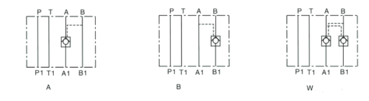
*All manufacturer names and part numbers are used for reference only.
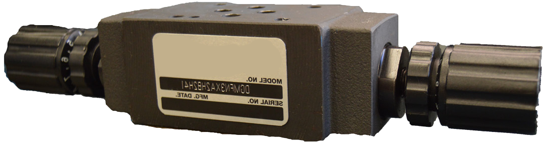
DGMFN3 41
Module height 40 mm. D03 mounting. Removable hand knobs. 18-month warranty.
These valves control flow with an adjustable orifice that is not pressure compensated. They allow meter-in or meter-out control.
Model code breakdown
- 1
- DGMFN3
- Flow control valve
- 2
- X
- Flow control direction
- 3
- A
- Control function location
- 4
- 2
- Control needle type
- 5
- H
- Adjustment type
- 6
- B
- Second-line control
- 7
- 2
- Control needle type, second line
- 8
- H
- Adjustment type, second line
- 9
- 41
- Series 41
Flow control valve
DGMFN3
Flow control direction
Relative to the machine actuator.
| Code | Description |
|---|---|
| X | Meter-in control, for lines A and B |
| Y | Meter-out control, for lines A and B |
Control function location
Single model, or the first line of the dual model.
| Code | Description |
|---|---|
| A | Line A (single model, or first line of the dual model) |
| B | Meter-out control, for lines A and B |
Control needle type
Single model, or the first line of the dual model.
| Code | Description |
|---|---|
| 2 | Standard control |
Adjustment type
Single model, or the first line of the dual model.
| Code | Description |
|---|---|
| H | Knob |
| W* | Screw with locknut |
Second-line control
Omit on single-line models.
| Code | Description |
|---|---|
| B | Line B (use on dual models when A is specified) |
Control needle type, second line
Omit on single-line models.
| Code | Description |
|---|---|
| 2 | Standard control |
Adjustment type, second line
Omit on single-line models.
| Code | Description |
|---|---|
| H | Knob |
Series 41
Subject to change.
* Available in Reman only.
Operation
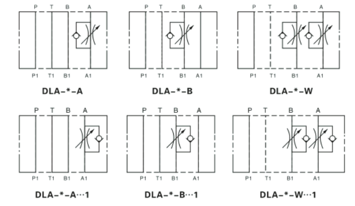
*All manufacturer names and part numbers are used for reference only.
Weight
| Model | Weight (lb) |
|---|---|
| DGMC | 2.9 |
| DGMC2 | 5.5 |
| DGMR (1) | 2.9 |
| DGMX | 2.9 |
| DGMDC | 2.2 |
| DGMPC | 1.8 |
| DCMFN | 2.2 |
Mounting bolts
The mounting bolt length used to install the assembly depends on how many valves are used.
D03 bolt kits
Use this guide to choose the kit.
| Valve | Length | Kit |
|---|---|---|
| Valve only | 1.75 in (44.45 mm) | BK02-156494 |
| Valve + 1 module | 3.5 in (88.9 mm) | BK466851 |
| Valve + 2 modules | 5 in (127 mm) | BK466855 |
| Valve + 3 modules | 6.5 in (165.10 mm) | BK466858 |
Type H adjuster
The setting is adjusted by loosening the M4 locking screw and turning the knob to the desired position. Tighten the M4 locking screw again after adjusting. Available on DGMC-3, DGMFN-3, and DGMX-3.
Turn clockwise to increase pressure and counterclockwise to decrease pressure.
D03 pilot operated check valves
Check cracking pressure 14.5 psi. Sandwich thickness 40 mm.
| Valve | Description |
|---|---|
| DGMPC-3ABK BAK-41 | Dual crossover checks |
| DGMPC-3ABK-41 | Check in "A", piloted from "B" |
| DGMPC-3BAK-41 | Check in "B", piloted from "A" |
D03 reducing valves
Pressure reduced in "P", piloted from "P". H = pressure adjustment with a knob. N = 1/4" NPT gauge port. Sandwich thickness is 40 mm.
| Valve | Description |
|---|---|
| DGMX2 3 PP BHN41 | Adjustment range 50 to 1000 psi, reduced in P |
| DGMX2 3 PP CHN41 | Adjustment range 145 to 2000 psi, reduced in P |
| DGMX2 3 PP FHN41 | Adjustment range 290 to 3625 psi, reduced in P |
| DGMX2 3 PA BHN41 | Adjustment range 50 to 1000 psi, reduced in A |
| DGMX2 3 PA CHN41 | Adjustment range 145 to 2000 psi, reduced in A |
| DGMX2 3 PA FHN41 | Adjustment range 290 to 3625 psi, reduced in A |
| DGMX2 3 PB BHN41 | Adjustment range 50 to 1000 psi, reduced in B |
| DGMX2 3 PB CHN41 | Adjustment range 290 to 3625 psi, reduced in B |
| DGMX2 3 PB FHN41 | Adjustment range 290 to 3625 psi, reduced in B |
D03 flow control valves
H = pressure adjustment with a knob. W = pressure adjustment with a screw and locknut. Sandwich thickness is 40 mm.
| Valve | Description |
|---|---|
| DGMFN 3 Y A2 W/H 41 | Flow control, meter-out, port A |
| DGMFN 3 X A2 W/H 41 | Flow control, meter-in, port A |
| DGMFN 3 Y B2 W/H 41 | Flow control, meter-out, port B |
| DGMFN 3 X B2 W/H 41 | Flow control, meter-in, port B |
| DGMFN 3 Y A2 W/H B2 W/H 41 | Flow control, meter-out, ports A and B |
| DGMFN 3 X A2 W/H B2 W/H 41 | Flow control, meter-in, ports A and B |
D03 check valves
Sandwich thickness 40 mm.
| Valve | Description |
|---|---|
| DGMDC 3XTL 41 | Free flow away from the actuator, check in port T, 5 psi |
| DGMDC 3XAL 41 | Free flow away from the actuator, check in port A, 5 psi |
| DGMDC 3XBL 41 | Free flow away from the actuator, check in port B, 5 psi |
| DGMDC 3YPL 41 | Free flow toward the actuator, check in port P, 5 psi |
| DGMDC 3XTR 41 | Free flow away from the actuator, check in port T, 50 psi |
| DGMDC 3XAR 41 | Free flow away from the actuator, check in port A, 50 psi |
| DGMDC 3XBR 41 | Free flow away from the actuator, check in port B, 50 psi |
| DGMDC 3YPR 41 | Free flow toward the actuator, check in port P, 50 psi |
D03 relief valves
H = pressure adjustment with a knob. W = pressure adjustment with a screw and locknut. Sandwich thickness is 40 mm.
| Valve | Description |
|---|---|
| DGMC3 PTB W/H 41 | Pressure at "P" relieved to "T", 44 psi to 1450 psi (3-100 bar) |
| DGMC3 ATB W/H 41 | Pressure at "A" relieved to "T", 44 psi to 1450 psi (3-100 bar) |
| DGMC3 BTB W/H 41 | Pressure at "B" relieved to "T", 44 psi to 1450 psi (3-100 bar) |
| DGMC2 3ATB W/H BTB W/H 41 | Dual relief. Pressure at "A" relieved to "T". Pressure at port "B" relieved to "T", 47 psi to 1450 psi (3-100 bar) |
| DGMC3 PTC W/H 41 | Pressure at "P" relieved to "T", 500 psi to 2000 psi |
| DGMC3 ATC W/H 41 | Pressure at "A" relieved to "T", 500 psi to 2000 psi |
| DGMC3 BTC W/H 41 | Pressure at "B" relieved to "T", 500 psi to 2000 psi |
| DGMC2 3ATC W/H BTC W/H 41 | Dual relief. Pressure at "A" relieved to "T". Pressure at port "B" relieved to "T", 500 psi to 2000 psi |
| DGMC2 3ATF W/H BTF W/H 41 | Dual relief. Pressure at "A" relieved to "T". Pressure at port "B" relieved to "T", 800 psi to 3600 psi |
| DGMC3 PTF H 41 | Pressure at "P" relieved to "T", 800 psi to 3600 psi |
| DGMC3 ATF H 41 | Pressure at "A" relieved to "T", 800 psi to 3600 psi |
| DGMC3 BTF H 41 | Pressure at "B" relieved to "T", 800 psi to 3600 psi |
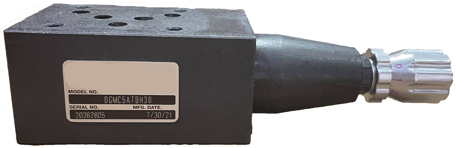
DGMC5 30 and DGMC25 30
Module height 55 mm. D05 mounting. Removable hand knob. 18-month warranty.
The relief valve dumps system pressure from line A, B, or P to line T. Pressure is set on the valve with knobs.
Model code breakdown
- 1
- DGMC
- Relief valve
- 2
- 2
- Type
- 3
- 5
- D05 interface
- 4
- AT
- First function
- 5
- B
- Pressure adjustment range, first function
- 6
- H
- Adjustment and lock method, first function
- 7
- BT
- Second function
- 8
- B
- Pressure adjustment range, second function
- 9
- H
- Adjustment and lock method, second function
- 10
- 30
- Series 30
Relief valve
DGMC
Type
| Code | Description |
|---|---|
| 2 | Dual relief function |
| — | Omit for single relief function |
D05 interface
5
First function
Single relief, or the first line of dual models.
| Code | Pressure limited at | Relieves to | Use |
|---|---|---|---|
| PT | P | T | Single only |
| AB* | A | B | Single, or dual with BA |
| BA | B | A | Single only |
| AT | A | T | Single, or dual with BT |
| BT | B | T | Single only |
Pressure adjustment range, first function
| Code | Range |
|---|---|
| A | 4-52 bar (60-750 psi) |
| B | 4-100 bar (60-1450 psi) |
| F | 4-200 bar (60-2900 psi) |
| G | 4-310 bar (60-4500 psi) |
Adjustment and lock method, first function
| Code | Description |
|---|---|
| H | Knob |
| W* | Screw with locknut |
Second function
Second line of dual models. Omit on single-line models.
| Code | Pressure limited at | Relieves to | Use |
|---|---|---|---|
| BA* | B | A | Dual with AB |
| BT | B | T | Dual with AT |
Pressure adjustment range, second function
| Code | Range |
|---|---|
| A | 4-52 bar (60-750 psi) |
| B | 4-100 bar (60-1450 psi) |
| F | 4-200 bar (60-2900 psi) |
| G | 4-310 bar (60-4500 psi) |
Adjustment and lock method, second function
| Code | Description |
|---|---|
| H | Knob |
| W* | Screw with locknut |
Series 30
Subject to change.
* Available in Reman only.
Operation
*All manufacturer names and part numbers are used for reference only.
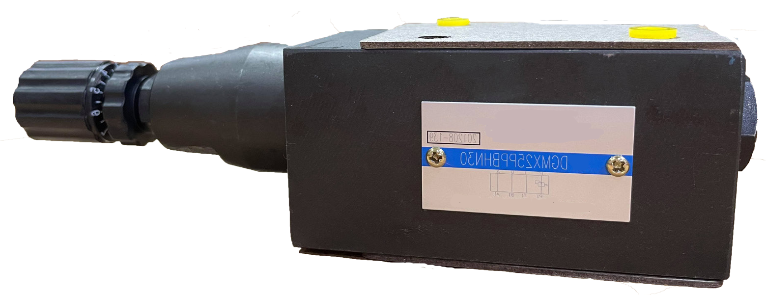
DGMX25 30
Module height 60 mm. D05 mounting. Removable hand knob. 18-month warranty.
Pressure reducing valves hold a reduced outlet pressure regardless of inlet pressure. Pressure is reduced in line P and set with the knob.
The pressure reducing valve passage is normally open. If pilot pressure is higher than the valve setting, the spring closes the valve.
Model code breakdown
- 1
- DGMX25
- Pressure reducing valve
- 2
- PA
- Function ports
- 3
- B
- Pressure adjustment range
- 4
- H
- Pressure adjustment
- 5
- N
- Gauge port
- 6
- 30
- Series 30
Pressure reducing valve
DGMX25
Function ports
| Code | Description |
|---|---|
| PA | Pressure reducing function in line P, piloted from A |
| PB | Pressure reducing function in line P, piloted from B |
| PP | Pressure reducing function in line P, piloted from P |
Pressure adjustment range
| Code | Range |
|---|---|
| B | 3.5-70 bar (50-1000 psi) |
| C | 10-140 bar (145-2000 psi) |
| F | 20-250 bar (290-3625 psi) |
Pressure adjustment
| Code | Description |
|---|---|
| H | Knob |
Gauge port
| Code | Description |
|---|---|
| N | 1/4" NPT |
Series 30
Subject to change.
Operation
*All manufacturer names and part numbers are used for reference only.
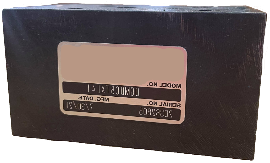
DGMDC5 41
Module height 55 mm. D05 mounting. Same-day shipping. 18-month warranty.
These valves allow free flow in one direction and block flow in the opposite direction.
Model code breakdown
Direct check valve
DGMDC5
Flow direction
| Code | Description |
|---|---|
| X | Free flow away from the actuator |
| Y | Free flow toward the actuator |
Check location
| Code | Description |
|---|---|
| A | Line A |
| B | Line B |
| P | Line P, with free flow toward the actuator (Y in 1) |
| T | Line T, with free flow away from the actuator (X in 1) |
Cracking pressure
| Code | Pressure |
|---|---|
| L | 5 psi (0.34 bar) |
| R | 60 psi (4.14 bar) |
Series 41
Subject to change.
Operation
*All manufacturer names and part numbers are used for reference only.
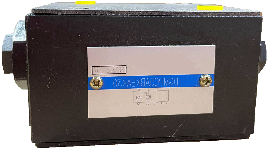
DGMPC5 30
Module height 50 mm. D05 mounting. Cracking pressure 14.5 psi (1 bar). 18-month warranty.
These valves allow flow through one or both service lines A or B, and let flow travel the opposite way through the other service line by a pilot operated check. If there is pressure in one service line, the check valve opens in the other service line.
Model code breakdown
- 1
- DGMPC5
- Pilot operated check valve
- 2
- AB
- Function
- 3
- K
- Cracking pressure
- 4
- BA
- Second function
- 5
- K
- Cracking pressure, second function
- 6
- 30
- Series 30
Pilot operated check valve
DGMPC5
Function
| Code | Description |
|---|---|
| AB | Check in line A, piloted from line B |
| BA | Check in line B, piloted from line A |
Cracking pressure
| Code | Pressure |
|---|---|
| K | 1 bar (14.5 psi) |
Second function
Second line of dual models. Omit on single-line models.
| Code | Description |
|---|---|
| BA | Check in line B, piloted from line A |
Cracking pressure, second function
| Code | Pressure |
|---|---|
| K | 1 bar (14.5 psi) |
Series 30
Subject to change.
Operation
*All manufacturer names and part numbers are used for reference only.
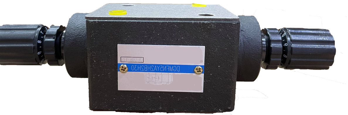
DGMFN5 41
Module height 55 mm. D05 mounting. Removable hand knobs. 18-month warranty.
These valves control flow with an adjustable orifice that is not pressure compensated. They allow meter-in or meter-out control.
Model code breakdown
- 1
- DGMFN5
- Flow control valve
- 2
- X
- Flow control direction
- 3
- A
- Control function location
- 4
- 2
- Control needle type
- 5
- H
- Adjustment type
- 6
- B
- Second-line control
- 7
- 2
- Control needle type, second line
- 8
- H
- Adjustment type, second line
- 9
- 41
- Series 41
Flow control valve
DGMFN5
Flow control direction
Relative to the machine actuator.
| Code | Description |
|---|---|
| X | Meter-in control, for lines A and B |
| Y | Meter-out control, for lines A and B |
Control function location
Single model, or the first line of the dual model.
| Code | Description |
|---|---|
| A | Line A (single model, or first line of the dual model) |
| B | Meter-out control, for lines A and B |
Control needle type
Single model, or the first line of the dual model.
| Code | Description |
|---|---|
| 2 | Standard control |
Adjustment type
Single model, or the first line of the dual model.
| Code | Description |
|---|---|
| H | Knob |
| W* | Screw with locknut |
Second-line control
Omit on single-line models.
| Code | Description |
|---|---|
| B | Line B (use on dual models when A is specified) |
Control needle type, second line
Omit on single-line models.
| Code | Description |
|---|---|
| 2 | Standard control |
Adjustment type, second line
Omit on single-line models.
| Code | Description |
|---|---|
| H | Knob |
Series 41
Subject to change.
* Available in Reman only.
Operation
*All manufacturer names and part numbers are used for reference only.
Weight
| Model | Weight (lb) |
|---|---|
| DGMC | 3.4 |
| DGMC2 | 4.7 |
| DGMX | 3.4 |
| DGMDC | 2.7 |
| DGMPC | 2.0 |
| DGMFN | 2.2 |
Mounting bolts
The mounting bolt length used to install the assembly depends on how many valves are used.
D05 bolt kits
Bolt kits are offered for certain combinations. Use this guide to determine the kit.
| Valve | Length | Kit |
|---|---|---|
| D05 valve only | 1.50 in (38.1 mm) | BKDG01633 |
| Valve + 50 mm | 3.75 in (95.25 mm) | BK255654 |
| Valve + 55 mm | 4.00 in (101.6 mm) | BK255689 |
| Valve + 60 mm | 4.00 in (101.6 mm) | BK255689 |
| Valve + any 2 modules | 6.00 in (152.4 mm) | BK255657 |
Type H adjuster
The setting is adjusted by loosening the M4 locking screw and turning the knob to the desired position. Tighten the M4 locking screw again after adjusting. Available on DGMC-3, DGMFN-3, and DGMX-3.
Turn clockwise to increase pressure and counterclockwise to decrease pressure.
D05 pilot operated check valves
Check cracking pressure 14.5 psi. Sandwich thickness is 50 mm.
| Valve | Description |
|---|---|
| DGMPC-5ABK BAK-30 | Dual crossover checks |
| DGMPC-5ABK-30 | Check in "A", piloted from "B" |
| DGMPC-5BAK-30 | Check in "B", piloted from "A" |
D05 reducing valves
Pressure reduced in "P", piloted from "P", and reduced in "A" and "B". H = pressure adjustment with a knob. N = 1/4" NPT gauge port. W = pressure adjustment with a screw and locknut. S = SAE 7/16-20 gauge port. Sandwich thickness is 60 mm.
| Valve | Description |
|---|---|
| DGMX2 5 PPB HN/WS 30 | Adjustment range 50 to 1000 psi, reduced in P |
| DGMX2 5 PPC HN/WS 30 | Adjustment range 145 to 2000 psi, reduced in P |
| DGMX2 5 PPF HN/WS 30 | Adjustment range 290 to 3625 psi, reduced in P |
| DGMX2 5 PAB HN/WS 30 | Adjustment range 50 to 1000 psi, reduced in A |
| DGMX2 5 PAC HN/WS 30 | Adjustment range 145 to 2000 psi, reduced in A |
| DGMX2 5 PAF HN/WS 30 | Adjustment range 290 to 3625 psi, reduced in A |
| DGMX2 5 PBB HN/WS 30 | Adjustment range 50 to 1000 psi, reduced in B |
| DGMX2 5 PBC HN/WS 30 | Adjustment range 145 to 2000 psi, reduced in B |
| DGMX2 5 PBF HN/WS 30 | Adjustment range 290 to 3625 psi, reduced in B |
D05 flow control valves
H = pressure adjustment with a knob. W = pressure adjustment with a screw and locknut. Sandwich thickness is 55 mm.
| Valve | Description |
|---|---|
| DGMFN 5 Y A2 W/H 30 | Flow control, meter-out, port A |
| DGFN 5 X A2 W/H 30 | Flow control, meter-in, port A |
| DGMFN 5 Y B2 W/H 30 | Flow control, meter-out, port B |
| DGMFN 5 X B2 W/H 30 | Flow control, meter-in, port B |
| DGMFN 5 Y A2 W/H B2 W/H 30 | Flow control, meter-out, ports A and B |
| DGMFN 5 X A2 W/H B2 W/H 30 | Flow control, meter-in, ports A and B |
D05 check valves
Sandwich thickness is 55 mm.
| Valve | Description |
|---|---|
| DGMDC 5 X TL-41 | Free flow away from the actuator, check in port T, 5 psi |
| DGMDC 5 X AL-41 | Free flow away from the actuator, check in port A, 5 psi |
| DGMDC 5 X BL-41 | Free flow away from the actuator, check in port B, 5 psi |
| DGMDC 5 Y PL-41 | Free flow toward the actuator, check in port P, 5 psi |
| DGMDC 5 X TR-41 | Free flow away from the actuator, check in port T, 60 psi |
| DGMDC 5 X AR-41 | Free flow away from the actuator, check in port A, 60 psi |
| DGMDC 5 X BR-41 | Free flow away from the actuator, check in port B, 60 psi |
| DGMDC 5 Y PR-41 | Free flow toward the actuator, check in port P, 60 psi |
D05 relief valves
H = pressure adjustment with a knob. W = pressure adjustment with a screw and locknut. S = SAE 7/16-20 gauge port. Sandwich thickness is 55 mm.
| Valve | Description |
|---|---|
| DGMC5 PTB H 30 | Pressure at "P" relieved to "T", 48 psi to 1450 psi |
| DGMC5 ATB H 30 | Pressure at "A" relieved to "T", 48 psi to 1450 psi |
| DGMC5 BTB H 30 | Pressure at "B" relieved to "T", 48 psi to 1450 psi |
| DGMC2 5 ATB W BTB W/S 30 | Dual relief. Pressure at "A" relieved to "T". Pressure at port "B" relieved to "T", 48 psi to 1450 psi |
| DGMC2 5 ATB H BTB H 30 | Dual relief. Pressure at "A" relieved to "T". Pressure at port "B" relieved to "T", 48 psi to 1450 psi |
| DGMC5 PTC H 30 | Pressure at "P" relieved to "T", 100 psi to 2000 psi |
| DGMC5 ATC H 30 | Pressure at "A" relieved to "T", 100 psi to 2000 psi |
| DGMC5 BTC H 30 | Pressure at "B" relieved to "T", 100 psi to 2000 psi |
| DGMC2 5 ATC W BTC W/S 30 | Dual relief. Pressure at "A" relieved to "T". Pressure at port "B" relieved to "T", 100 psi to 2000 psi |
| DGMC2 5 ATC H BTC H 30 | Dual relief. Pressure at "A" relieved to "T". Pressure at port "B" relieved to "T", 100 psi to 2000 psi |
| DGMC5 PTF H 30 | Pressure at "P" relieved to "T", 125 psi to 3600 psi |
| DGMC5 ATF H 30 | Pressure at "A" relieved to "T", 125 psi to 3600 psi |
| DGMC5 BTF H 30 | Pressure at "B" relieved to "T", 125 psi to 3600 psi |
| DGMC2 5 ATF W BTF W/S 30 | Dual relief. Pressure at "A" relieved to "T". Pressure at port "B" relieved to "T", 125 psi to 3600 psi |
| DGMC2 5 AFT H BTF H 30 | Dual relief. Pressure at "A" relieved to "T". Pressure at port "B" relieved to "T", 125 psi to 3600 psi |
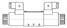
Modular stack valve mounting location
| Model | Function | Location |
|---|---|---|
| DGMDC | Direct check | Mounted closest to the directional valve. |
| DGMPC | Pilot check | Mounted closest to the directional valve. |
| DGMFN | Flow control | Mounted between the check valve and the relief valve. |
| DGMX | Pressure reducing | Mounted between the check valve and the relief valve. |
| DGMC | Relief | Mounted closest to the subplate or manifold. |
Directional valve
Check

Flow control

Pressure reducing

Relief

Subplate or manifold
Modular stack hydraulic valves: industrial applications, functions, and replacements
Modular stack hydraulic valves, also known as sandwich valves, add pressure, flow, and check functions to industrial hydraulic circuits without extra piping between each component. They mount between the directional valve and a compatible subplate or manifold, forming a compact assembly that simplifies the design, maintenance, and repair of hydraulic systems.
Technical Union (TU) supplies hydraulic components for industrial applications, maintenance, and equipment replacement. For companies looking for hydraulic modular valves, stack valves, or replacements for existing components, identify the required function, nominal size, and mounting interface before selecting an alternative.
What functions do stack hydraulic valves provide?
Modular valves are selected according to the circuit needs and the behavior to be controlled.
Pressure relief valves
Relief valves limit the maximum circuit pressure to protect pumps, cylinders, hydraulic motors, and other components against overpressure.
Typical applications:
- Industrial hydraulic presses.
- Metal forming and stamping machines.
- Hydraulic power units (HPU).
- Workholding and clamping systems.
- Manufacturing and industrial automation equipment.
Pressure reducing valves
They hold a lower pressure in a given section of the circuit when a machine function needs a pressure different from the main circuit.
Typical applications:
- CNC machine tools.
- Hydraulic clamping systems.
- Industrial assembly equipment.
- Auxiliary circuits on production machinery.
- Systems with different hydraulic-force requirements.
Flow control valves
They regulate the flow through a section of the system to control actuator speed, according to the circuit design and the valve characteristics.
Typical applications:
- Speed control of hydraulic cylinders.
- Feed and positioning of machine tools.
- Material-handling equipment.
- Industrial automation systems.
- Production machinery with controlled hydraulic movements.
Check valves and pilot-operated check valves
They allow oil to pass in one direction and block reverse flow. Pilot-operated versions open the passage under specified pilot conditions.
Typical applications:
- Hydraulic workholding.
- Cylinder positioning circuits.
- Lifting and handling equipment.
- Industrial systems that must hold a hydraulic position.
Selection should consider the load conditions and the safety requirements of the system, especially in lifting applications.
Counterbalance and sequence valves
Depending on the configuration, counterbalance valves help control hydraulically driven loads, while sequence valves start a function when a set pressure condition is reached.
Typical applications:
- Hydraulic motion and positioning systems.
- Clamping and pressing equipment.
- Assembly machines.
- Circuits with sequential hydraulic movements.
- Industrial equipment with loads that need control during motion.
Industries that use hydraulic modular valves
Stack valves are used in a wide range of installations where pressure, flow, check, or sequence must be controlled in hydraulic circuits.
Metalworking: presses, press brakes, hydraulic shears, stamping machines, forming equipment, and clamping systems.
Manufacturing and industrial automation: production lines, assembly stations, special machines, positioning systems, and automated equipment.
Machine tools: machining centers, CNC lathes, milling machines, hydraulic clamping systems, and workholding devices.
Plastics: injection-molding machines, hydraulic mold-clamping systems, and auxiliary production equipment.
Packaging and converting: processing machinery, cutting equipment, pressing systems, and production lines with hydraulic drives.
Wood and paper: presses, processing equipment, cutting machinery, and hydraulic clamping systems.
Industrial maintenance and hydraulic repair: replacement of worn valves, hydraulic power unit repair, circuit upgrades, and preventive machinery maintenance.
Replacing stack valves from other brands
When a hydraulic valve leaks, loses pressure, operates unevenly, or is hard to get parts for, it can be worth evaluating a compatible modular replacement valve.
Industrial manufacturers use standardized mounting interfaces on many valve families. That makes it possible to evaluate alternatives from different brands without necessarily changing the existing subplate or manifold.
Brands buyers may find on their equipment include:
- Bosch Rexroth.
- Parker.
- Eaton Vickers.
- Yuken.
- Atos.
- Other industrial hydraulic valve brands.
Compatibility must be checked for each model. In particular, stack valves must match the mounting interface, the hydraulic function, and the circuit configuration. Similar outside dimensions are not enough.
What should be checked before replacing a valve?
- Brand and model: identify the full code of the installed valve.
- Mounting interface: confirm the standard and size, when they are specified.
- Hydraulic function: determine whether a relief, reducing, flow control, check, counterbalance, or sequence valve is required.
- Pressure and flow: confirm that the alternative meets the system's operating requirements.
- Ports and internal connections: check the galleries, oil passages, and the drain or pilot conditions that apply.
- Stack configuration: confirm the mounting position and the order of the valves in the stack.
A correct evaluation helps reduce unnecessary modifications, avoid incompatibilities, and select a suitable replacement for the application.
Supply of hydraulic components for Latin America
Technical Union (TU) supplies hydraulic components for industrial companies, distributors, repair shops, and maintenance departments looking for alternatives for their equipment.
If you need modular stack hydraulic valves, repair components, or replacements for industrial valves, contact TU to identify a solution based on the brand, model, and requirements of your application.
Looking for a replacement for an installed hydraulic valve? Send the brand, model, or a photo of the nameplate, along with the required function and the available pressure and flow data, to help evaluate the right component.
See the TU modular stack hydraulic valves page for more information and to request assistance.